
Wednesday, September 30, 2015
A Cheap Sonar Module
For less than $1, I bought a HC-SR04 sonar module on eBay. It can't get cheaper than this.
 I was a little disturbed first when I saw the circuit board. Two of the ICs have no labels. And the layout appears different than other HC-SR04 module. A quick test seemed to confirm it actually worked.

Sunday, September 27, 2015
A Lithium Ion Battery USB Charger
A simple linear battery charger that draws power from a USB port is designed for 14500 lithium ion battery (which is about the same size as a AA battery). The circuit diagram is shown below with a Linear Tech LDO, but others LDO can be used.


The actually construction uses an Analog Device LDO, which features a comparator that is used to indicate the charging completion.

Wednesday, June 3, 2015
1W Cool and Warm White LEDs
The 1W cool white (6000-6500K) and warm white (3000-3500K) LEDs are driven by 350mA. The LEDs are mounted on 20mm Aluminum base heat sink plate. The forward voltages after the temperature stabilizes, which is quite warm are 3.18V and 3.04V respectively. The difference could be due to that the two types are from different vendors. The plates are hot, probably over 70C (cannot touch for more than 1-2 seconds). The LEDs seem fairly tolerant of over current; it survives 1A current with the forward voltage at 4.2V. That's why some of the cheap LED flashlight can get away with direct battery power with any electronics.

The image is taken with 1/2000s exposure with f/8.0; the center of LEDs are saturated. If we take the measurements at the rims, the cool white LED has RGB composition of .60, .56, .77 and the warm LED .80, .56, .47 .
Here eight 1W cool white LEDs are mounted to a desklamp replacing a 12W fluorescent tube. A 350mA constant current power supply module drives the 8 LEDs in series.


After some time, I had two LEDs in the lamp failed. The faulty LED would started blinking; it shut itself off probably due to overheating then recovered after it cooled off. The forward voltage of the faulty LED becomes much higher: starts off around 3.8V and would increase rather than decrease as it heats up until shutoff; it is still operable at lower current. To increase the reliability of lamp, I made them into two parallel strings, so they operate at much lower current at the expense of lower brightness (but still plenty of light).
The image is taken with 1/2000s exposure with f/8.0; the center of LEDs are saturated. If we take the measurements at the rims, the cool white LED has RGB composition of .60, .56, .77 and the warm LED .80, .56, .47 .
Here eight 1W cool white LEDs are mounted to a desklamp replacing a 12W fluorescent tube. A 350mA constant current power supply module drives the 8 LEDs in series.
After some time, I had two LEDs in the lamp failed. The faulty LED would started blinking; it shut itself off probably due to overheating then recovered after it cooled off. The forward voltage of the faulty LED becomes much higher: starts off around 3.8V and would increase rather than decrease as it heats up until shutoff; it is still operable at lower current. To increase the reliability of lamp, I made them into two parallel strings, so they operate at much lower current at the expense of lower brightness (but still plenty of light).
Thursday, May 28, 2015
BeagleBone Black Display
BeagleBone Black is a nice little board, but mine came with no HDMI display: the monitor could not detect a HDMI signal. I tried different monitors and cables with same result. I researched online and tried different versions of software distribution, but no luck. Although it is not essential to have the HDMI display, it is a little upsetting to miss this feature. As my frustration grew, I read someone wrote that his problem was with the micro HDMI connector. With naked eye, there did not seem anything wrong. When I looked under a microscope, I noticed that one pin might not solder correctly. I quickly verified the broken continuity. After slight touchup with a fine solder tip under a microscope, the HDMI display miraculous started to work. It turned out that Pin 19 (+5V) was loose. Now it works nicely on an HDTV with 1920x1080 resolution (24Hz). The connector certainly did not come to my mind as the possible problem; people have mentioned about bad cables, but not the connector. In my experience, the interconnect contributes to the most hardware problems and should be the first thing to check. But in this case, the potential software issue seemed to loom large.
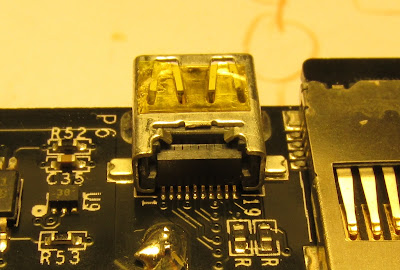
On a related one, when using a monitor, the software synergy is very useful for sharing keyboard and mouse.

On a related one, when using a monitor, the software synergy is very useful for sharing keyboard and mouse.
Wednesday, April 15, 2015
Reading AoE3
I read the 2nd edition from cover to cover in about 10 years. And I just read the 3rd edition in about one week. I used to say everything I knew about electronics I could find in AoE. Now I probably do know a few things that are not covered in the book.
The book cover has been upgraded from silver to flashier gold color. I don't fault them for considering it as the gold standard in books on electronics.
This book deserves a 5 star rating. The true value of the book is that it is not an academic text book. It contains a wealth of practical information, in charts, tables, and graphs, no other books come close. The jewel of the crown is the chapter on precision circuits. The chapter on noise is equally rich.
However, I did not like the elimination of the circuit ideas section and replacing it with a chapter review. Omitting the circuit construction is also a loss because prototyping and making the circuit board are an essential art that separates practitioners from theorists. I also lament the elimination of the chapter on RF. This book constantly refers the reader to the so-far unavailable "The x-Chapters" book; it is somewhat irritating to me that I'll have to get another book.
I wish it had fewer annoying trivial errors (how could you not catch a flipped diode on Fig 1.78?) ; 25 years ought to be enough to get it perfect.
So if you are a newcomer, you could still choose the 2nd edition because you can probably find a bargain now. But I won't let go my 2nd edition.
The new edition is 0.7" wider, 67 pages more with smaller font and narrower margin.

Tuesday, January 20, 2015
80486 PC: Power Supply
Power Supply
This particular PC power supply is rated 230W: 5V@23A, 12V@9A, -5V@0.5A and -12V@0.5A. There is no 3.3V output.

It takes 120V AC (with a switch for 220VAC). The AC color code is usually black for line, white for neutral and green for ground. The earth ground is tied to the chassis and is tied to the circuit ground. In this power supply, the line and the neutral are brought to a switch at the front panel. The switch connects them to a connector on the board (brown and blue wires) and to an AC socket to optionally power a monitor, a feature that disappeared later. It does not have a way to turn the power off electronically by software. The line is fused (5A/250V), but the fuse is soldered to the board, so not easily replaceable. A thermistor is used to limit the inrush current; it starts at 5 Ohms and drops to 0.2 Ohm at the full load of 3A. The AC input is filtered by capacitors and a common-mode choke. Then it is rectified by a diode bridge and filtered by two large capacitors (330uF 200V). These two capacitors are connected in series; depending on the 120/220V switch, they are either charged in series with the full wave rectifier or individually charged by half wave rectifier (a voltage doubler). This is how both 120V and 220V are accommodated. The maximum voltage is 2*120*sqrt(2)=340V. If the switch is closed (intended for 120V) but 220V is applied, the voltage would exceed the capacitors' rating. I wonder if any power supply is destroyed this way.

Now we have a high voltage DC to work with. The switching regulator is in the half-bridge configuration. Two power NPN 2SC3040 transistors (400V/8A) mounted on a heat sink drive a transformer primary. The secondary is diode rectified and filtered; the diodes are mounted on a heat sink. (For some reason, the heat sink is tied to the cathode of the 12V rectifier diode.) The circuit board is one-side; all components are on one side and all are through-hole. The only IC DBL494 is the pulse width modulation controller and is resided on the secondary. The base drive comes through a transformer. The frequency is about 32KHz. DBL494 has a 5V reference. The feedback is on 5V; the other voltages are not regulated and do vary with the load on 5V. When the 5V is unloaded, the 12V is only 10V. When 5A is drawn from the 5V, the 12V is 12V. DBL494 is powered from the 12V. An interesting question is, how does the secondary bootstrap itself?
The fan is often the source of irritating noise. The size of the fan is 3" x 3". The fan (12V/0.14A) is powered from the 12V. The fan is brushless and an outrunner (the magnet is out side); a Hall switch inside the fan does the communication.
| Pin | Signal | Description |
|---|---|---|
| P8.1 | Power Good | |
| P8.2 | +5 V | |
| P8.3 | +12 V | |
| P8.4 | −12 V | |
| P8.5 | Ground | |
| P8.6 | Ground | |
| P9.1 | Ground | |
| P9.2 | Ground | |
| P9.3 | −5 V | |
| P9.4 | +5 V | |
| P9.5 | +5 V | |
| P9.6 | +5 V | |
There are other power connectors for floppy drive and hard drive.
[I accidentally shorted something and the fuse was blown. The two power BJT were destroyed. Not sure how it happened. I might have touched the heat sink to the chassis ground. The fuse is not there to protect the components.]
Monday, January 19, 2015
Soda Can Wifi Antennas
Some clever folks posted the parabolic antennas made from beer cans. It is quick and easy to do. I made one for my router. Although the gain is not dramatic, I do see some improvement in SNR. The signal quality indicator goes up a few percent.

Subscribe to:
Posts (Atom)