In 2003, I bought an HP/Compaq Presario 2100 laptop, not the best purchase that I made. In this days of age, it is just not very useful even after I put in a solid-state hard drive and installed light-weight Linux desktop. It just could not handle the very basic functions of web surfing. But it seems such a waste to throw it out.
On the other hand, little single board computers, such as Raspberry Pi show great potential. They cost about 20 times less than what I paid for the laptop. But they do not come with a screen, keyboard/touchpad. I recently acquired an Asus Tinker Board, which has pretty impressive performance. With a fast microSD card, it can surf the web comfortably. When they are networked together (but having to settle for 100Mbps Ethernet), the laptop just serves as a terminal for the Tinker Board by running VNC. I found tigervnc to be the best. However, VNC does not pass audio. One solution is to connect the audio output to the laptop microphone input and run loopback to the speaker (pactl load-module module-loopback latency_msec=1). This arrangement proves to be quite usable even though the screen resolution is relatively low. If an external monitor is attached through HDMI, synergy can be used to share the keyboard and pointer.
Friday, August 31, 2018

Sunday, August 19, 2018
TI Simplelink BLE
Here we try out TI SimpleLink Bluetooth Low Energy (BLE) CC2650MODA+MSP432P401R Launchpad bundle ($35). MSP432P401R comes with an out-of-box demo with LEDs. We install the latest CCS 8.1.0 and SimpleLink MSP432P4 SDK (v2.20.00.12). From the SDK, we import outofbox_msp432p401r_MSP_EXP432P401R_tirtos_ccs and compile and upload. After that is successful, we download SimpleLink SDK BLE Plugin (simplelink_sdk_ble_plugin_1_40_00_42) and also BLE-Stack (ble_sdk_2_02_02_25).
We import from SimpleLink SDK BLE Plugin project_zero_MSP_EXP432P401R_tirtos_ccs. We compile and upload. When the USB is connected to a PC, two serial ports are created. On Linux they are /dev/ttyACM0 and ACM1. Connect to the serial port at 115200 baud, the following message comes up.
CC2650MODA draws about 160uA when idle, and 0.1uA when in reset. There is a 100K pull up resistor on the reset pin, which could contribute to 30uA if the reset pin is pulled low.
We import from SimpleLink SDK BLE Plugin project_zero_MSP_EXP432P401R_tirtos_ccs. We compile and upload. When the USB is connected to a PC, two serial ports are created. On Linux they are /dev/ttyACM0 and ACM1. Connect to the serial port at 115200 baud, the following message comes up.
Scanning for Bluetooth devices, "Project Zero" should come up. TI Android App SimpleLink SDK Explorer can be used for testing; it has a Project Zero interface to control the LED, read buttons, and send text. On Linux, we can use hcitool lescan to scan and gatttool to test--------- Project Zero Example ---------Initializing the user task, hardware, BLE stack and services.LEDService: Registered callbacks to application.ButtonService: registered callbacks to applicationDataService: Registered callbacks to application.LEDService: Registered service, 1 attributesButtonService: Registered service, 2 attributesDataService: Registered service, 2 attributes
gatttool -b A0:E6:F8:BD:EB:02 -IWhen both buttons are pressed, CC2650MODA is flashed. However, note the default project includes cc2640r2lp_simple_np_uart_pm_sble hex, which does not work with CC2650. We replace it with simple_np_cc2650bp_uart_pm_sbl_2_02_01_18a_merge. If there is some problem flashing, install SmartRF Flash Programmer 2 (v1.7.5).
[A0:E6:F8:BD:EB:02][LE]> connect
Attempting to connect to A0:E6:F8:BD:EB:02
Connection successful
[A0:E6:F8:BD:EB:02][LE]> primary
attr handle: 0x0001, end grp handle: 0x0007 uuid: 00001800-0000-1000-8000-00805f9b34fb
attr handle: 0x0008, end grp handle: 0x0008 uuid: 00001801-0000-1000-8000-00805f9b34fb
attr handle: 0x0009, end grp handle: 0x001b uuid: 0000180a-0000-1000-8000-00805f9b34fb
attr handle: 0x001c, end grp handle: 0x001e uuid: f0001110-0451-4000-b000-000000000000
attr handle: 0x001f, end grp handle: 0x0025 uuid: f0001120-0451-4000-b000-000000000000
attr handle: 0x0026, end grp handle: 0xffff uuid: f0001130-0451-4000-b000-000000000000
[A0:E6:F8:BD:EB:02][LE]> char-write-req 0x001e ff00ff
Characteristic value was written successfully
[A0:E6:F8:BD:EB:02][LE]> char-read-hnd 0x001e
Characteristic value/descriptor: ff 00 ff
CC2650MODA draws about 160uA when idle, and 0.1uA when in reset. There is a 100K pull up resistor on the reset pin, which could contribute to 30uA if the reset pin is pulled low.
Friday, July 13, 2018
Backup Camera
A backup camera with an LCD monitor can be purchased for about 30 USD. Some camera by itself is sold for less than 4 USD. The camera can be mounted at the rear license plate. The camera runs on 12V and outputs NTSC analog video signal. Nearly identical systems are marketed under various brand names. The specs are similar: 648x488 pixels, 420 TV lines camera; 4.3" 480 x 272 LCD monitor. The camera also comes with IR LEDs and light sensor. The system draws about 200mA at 12V and 230mA with LEDs on. The LCD monitor can take two video inputs; one of inputs takes priority. A DPDT switch can be used to toggle between the inputs.
The video quality is actually surprisingly good. The image sensor is claimed to be PC7070, but it is hard to find a data sheet. The best guess is that the sensor comes from Korea's PixelPlus, but there is not exact part listed. It could be similar to PC7080S: 648x488, 5.6um pixel, 1/4 inch optical format, power consumption 82mA/3.3V. OmniVision produces OV7950, which also has similar functionalities and a more detailed datasheet is available: 656x492, 6um pixel, 1/4 inch optical format.
The camera draws 78mA/12V, with LED 124mA. It can work down to 6V (5.6V with reduced video quality). The current draw is constant up to 14V (upper rated voltage). The LEDs only turn on when the voltage is greater than 10V, and draw more current as the voltage goes up (161mA/14V). The lens FOV is not advertised 135 degrees, but only 75 degree horizontal (94 degree diagonal).
The LCD display draws 23mA/12V when there is no video input and 122mA/12V when displaying video. The power seems switching regulated 104mA/14V, 166mA/9V and works down to about 6V (273mA).
The power input seems reverse polarity protected.
Although the world has gone digital, it is still appealing to run the analog video. It just works without complicated settings or software.
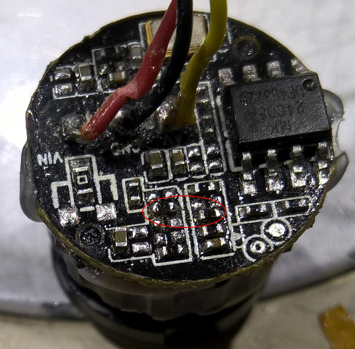
I opened up the back up camera that I bought on eBay for $3.72. The image quality is little poorer than the other one. The 4 LEDs are white light. After removing what appeared to be silicone gel and exposing the circuit board, I could see the imaging sensor and an EEPROM 24C08A, which is an I2C serial memory chip with 1Kx8 bits. It does not appear enough memory to supply the overlay image. So the OSD distance guideline displayed with the video is probably generated internally. I would like to remove the OSD and flip the image so it can be used as a front view camera.
The EEPROM has the three address lines grounded, so the 7-bit address is 0x50. The WP pin is also grounded allowing read and write. The I2C signals are pulled up to 3.3V with 4.7K. I started by shorting pin 4 (SDA) and pin 5 (GND) of the EEPROM. That probably forced the imager into the default state, but the default state enables the OSD with guidelines and a few extra numbers and letters and the exposure control seems a little different. So I'll have to get dump of the memory and make mods.
 I also came across a preliminary PC7070K datasheet, dated Oct. 2013. It describes the wire-strapping function: the state of the I/O pins determines the chip mode. The circuit board clearly has a few pull-up and pull-down resistors and un-populated footprints. It only took a few guesses to find the pads to turn off guidelines and disable image mirroring. Now it can be used for front view camera. The focus is a little close (as it is intended as a backup camera). The focus adjustment is fixed with epoxy, so it would take a little effort to make adjustment.
The video quality is actually surprisingly good. The image sensor is claimed to be PC7070, but it is hard to find a data sheet. The best guess is that the sensor comes from Korea's PixelPlus, but there is not exact part listed. It could be similar to PC7080S: 648x488, 5.6um pixel, 1/4 inch optical format, power consumption 82mA/3.3V. OmniVision produces OV7950, which also has similar functionalities and a more detailed datasheet is available: 656x492, 6um pixel, 1/4 inch optical format.
The camera draws 78mA/12V, with LED 124mA. It can work down to 6V (5.6V with reduced video quality). The current draw is constant up to 14V (upper rated voltage). The LEDs only turn on when the voltage is greater than 10V, and draw more current as the voltage goes up (161mA/14V). The lens FOV is not advertised 135 degrees, but only 75 degree horizontal (94 degree diagonal).
The LCD display draws 23mA/12V when there is no video input and 122mA/12V when displaying video. The power seems switching regulated 104mA/14V, 166mA/9V and works down to about 6V (273mA).
The power input seems reverse polarity protected.
Although the world has gone digital, it is still appealing to run the analog video. It just works without complicated settings or software.
I opened up the back up camera that I bought on eBay for $3.72. The image quality is little poorer than the other one. The 4 LEDs are white light. After removing what appeared to be silicone gel and exposing the circuit board, I could see the imaging sensor and an EEPROM 24C08A, which is an I2C serial memory chip with 1Kx8 bits. It does not appear enough memory to supply the overlay image. So the OSD distance guideline displayed with the video is probably generated internally. I would like to remove the OSD and flip the image so it can be used as a front view camera.
The EEPROM has the three address lines grounded, so the 7-bit address is 0x50. The WP pin is also grounded allowing read and write. The I2C signals are pulled up to 3.3V with 4.7K. I started by shorting pin 4 (SDA) and pin 5 (GND) of the EEPROM. That probably forced the imager into the default state, but the default state enables the OSD with guidelines and a few extra numbers and letters and the exposure control seems a little different. So I'll have to get dump of the memory and make mods.
Friday, June 22, 2018
PX4 on STM32F4Discovery
We'll try to run the PX4 firmware on the STM32F4Discovery board. Some documentation can be found here. We'll try to run everything from Linux.
First, we build the PX4 bootloader for f4discovery. There is a specific makefile target, make px4discovery_bl. To flash the bootloader, we can use texane stlink, which we will build. After installing it, we can run stlink-gui and download the bootloader through the mini USB port, detected as STMicroelectronics ST-LINK/V2.
Then we build the PX4 firmware with make px4-stm32f4discovery_default. We connect to the micro USB port; it is detected as PX4 BL DISCOVERY and /dev/ttyACM0 port is created. To flash, make px4-stm32f4discovery_default upload.
Connect a USB Serial adapter to PA3 (RX) and PA2 (TX), and run screen /dev/ttyUSB0 57600 to access NuttX terminal. The boot message,
sercon: Registering CDC/ACM serial driversercon: Successfully registered the CDC/ACM serial driverHW arch: PX4_STM32F4DISCOVERYFW git-hash: 7a82c777b28c49b3476be3da716984e6bdc987a9FW version: 7.82.77 0 (122834176)OS: NuttXOS version: Release 7.22.0 (118882559)OS git-hash: 63775322bf25adb406594f8e610122fe0cef2f7aBuild datetime: Jun 22 2018 22:25:57Build uri: BUILD_URIToolchain: GNU GCC, 4.9.3 20150529 (prerelease)MFGUID: 3138343532314719002e0034MCU: STM32F???, rev. ZUID: 2E0034:32314719:31383435nsh: mount: mount failed: No such file or directorynsh: tone_alarm: command not foundnsh: mkfatfs: mkfatfs failed: No such file or directorynsh: tone_alarm: command not foundnsh: tune_control: command not foundnsh: mtd: command not foundINFO [param] selected parameter default file /fs/microsd/paramsERROR [param] open '/fs/microsd/params' failed (2)nsh: rgbled: command not foundnsh: blinkm: command not foundnsh: rgbled_pwm: command not foundBAT_N_CELLS: curr: 0 -> new: 3ERROR [param] Parameter SYS_USE_IO not foundERROR [param] Parameter SYS_FMU_TASK not foundERROR [param] Parameter MNT_MODE_IN not foundERROR [param] Parameter MNT_MODE_OUT not foundnsh: dataman: command not foundnsh: gps: command not foundnsh: fmu: command not foundnsh: fmu: command not foundnsh: ms5611: command not foundnsh: ms5611: command not foundnsh: bst: command not foundnsh: adc: command not foundERROR [param] Parameter SENS_EN_LL40LS not foundERROR [param] Parameter SENS_EN_LL40LS not foundERROR [param] Parameter SENS_EN_SF0X not foundERROR [param] Parameter SENS_EN_SF1XX not foundERROR [param] Parameter SENS_EN_MB12XX not foundERROR [param] Parameter SENS_EN_TRANGER not foundERROR [param] Parameter SENS_EN_TFMINI not foundERROR [param] Parameter SENS_EN_LEDDAR1 not foundnsh: sensors: command not foundnsh: commander: command not foundnsh: send_event: command not foundnsh: load_mon: command not foundERROR [param] Parameter UAVCAN_ENABLE not foundERROR [param] Parameter SENS_EN_LL40LS not foundERROR [param] Parameter TRIG_MODE not foundnsh: fmu: command not foundnsh: tune_control: command not foundnsh: mavlink: command not foundnsh: mavlink: command not foundERROR [param] Parameter UAVCAN_ENABLE not foundnsh: mavlink: command not foundnsh: navigator: command not foundNo autostart ID foundnsh: ekf2: command not foundnsh: tone_alarm: command not foundERROR [param] Parameter MNT_MODE_IN not foundnsh: vmount: command not foundERROR [param] Parameter SDLOG_MODE not foundERROR [param] Parameter SDLOG_MODE not foundnsh: logger: command not foundnsh: mavlink: command not foundNuttShell (NSH)nsh> ERROR [parameters] failed to open param file: /fs/microsd/paramsERROR [parameters] param save failed (-1)nsh> helphelp usage: help [-v] [<cmd>][ dirname free mkrd rmdir umount? date help mh set unsetbasename dd hexdump mount sh usleepbreak df kill mv sleep xdcat echo ls mw testcd exec mb ps timecp exit mkdir pwd truecmp false mkfatfs rm unameBuiltin Apps:cubl_updateconfigmixernshtermparamperfpx4_simple_appreboottopuorbverserconserdisnsh> ver allHW arch: PX4_STM32F4DISCOVERYFW git-hash: 7a82c777b28c49b3476be3da716984e6bdc987a9FW version: 7.82.77 0 (122834176)OS: NuttXOS version: Release 7.22.0 (118882559)OS git-hash: 63775322bf25adb406594f8e610122fe0cef2f7aBuild datetime: Jun 22 2018 22:25:57Build uri: BUILD_URIToolchain: GNU GCC, 4.9.3 20150529 (prerelease)MFGUID: 3138343532314719002e0034MCU: STM32F???, rev. ZUID: 2E0034:32314719:31383435nsh>
Monday, June 11, 2018
Fan Speed Measurement
I have an application that requires the fan speed measurement. We can use some photo detector and a light source between the fan blades as an encoder.
The CdS photoresistor cell does not have the speed. A solar cell salvaged from a broken timer does respond adequately.
The solar cell is enclosed in a box with a small hole exposing the solar cell. A LED flashlight is pointed at the solar cell through the hole. The fan blades interrupts the light periodically. The voltage generated by the solar cell is digitized and the variations are detected and measured to determine the rate. The fan has 10 blades, at 1000RPM, the pulse rate is about 170Hz. The scope captures the signal,

 Note the rising edge is faster, but the falling edge still has the long tail.
The CdS photoresistor cell does not have the speed. A solar cell salvaged from a broken timer does respond adequately.
The solar cell is enclosed in a box with a small hole exposing the solar cell. A LED flashlight is pointed at the solar cell through the hole. The fan blades interrupts the light periodically. The voltage generated by the solar cell is digitized and the variations are detected and measured to determine the rate. The fan has 10 blades, at 1000RPM, the pulse rate is about 170Hz. The scope captures the signal,

If we use a laser point, which has a small beam spot, we get,

Tuesday, February 6, 2018
ESP32-PICO-D4
ESP32-PICO-D4 is a SIP (System-In-Package) module; it is measured about 7 x 7 x 1 mm and looks like a regular IC chip in a 40-pin QFN package. But it is actually packaged with ESP32, 4MB SPI Flash, 40MHz crystal, and passives. A picture of the inside shows that the Flash memory die is stacked on the top of the ESP32 die. Stacked die packaging has become a standard technique for miniaturization (5 dies can be stacked in 1.4mm package).
 |
| ESP32-PICO-KIT |
Arduino can be used for development, same as the ESP-WROOM-32 module, using the board "ESP32 Dev Module", or adding a custom board definition to the board file. The programmer toggles EN and BOOT to enter the Flash programming mode. For pin assignments, see pins_arduino.h for the specific board. In particular,
TX = 1;The two rows of header pins are documented here and here.
RX = 3;
SDA = 21;
SCL = 22;
SS = 5;
MOSI = 23;
MISO = 19;
SCK = 18;
DAC1 = 25;
DAC2 = 26;
Sunday, December 31, 2017
ESP32
Expressif comes out with ESP32, a more powerful successor to the popular ESP8266. The ESP-WROOM-32 module can be purchased for under $5. It is a 25.5 x18 x 3.1 mm PCB with printed antenna, and 38 castellation pins with 1.27mm (0.05") pitch. A very nice pinouts diagram can be found here.


The ESP32-D0WDQ6 supports 802.11n WiFi (2.4GHz) and Bluetooth v4.2. It contains dual Xtensa 32-bit LX6 cores (240MHz), 448KB ROM and 520KB SRAM. ESP-WROOM-32 has 4MB QSPI Flash. ESP32 can address up to 16MB external Flash. Parts of the internal SRAM (32KB for each core) serve as the cache for the slow SPI Flash.
There is also a development board which adds a 3.3V regulator and CP2102 USB to serial bridge chip. It has the more convenient 0.1" pitch pins. Or we can wire up like this,

Using Arduino is probably a good way to start. The support for esp32 is not included in Arduino by default; it can be installed following the instructions here .
IO0 has to be pulled low to enter the serial bootloader mode. esptool.py uses RTS for EN and DTR for IO0. For the ESP32 development board, CP2102 USB to serial bridge chip handles entering the bootloader mode. Here it is done manually. The connections are as follows,


There is also a development board which adds a 3.3V regulator and CP2102 USB to serial bridge chip. It has the more convenient 0.1" pitch pins. Or we can wire up like this,

Using Arduino is probably a good way to start. The support for esp32 is not included in Arduino by default; it can be installed following the instructions here .
IO0 has to be pulled low to enter the serial bootloader mode. esptool.py uses RTS for EN and DTR for IO0. For the ESP32 development board, CP2102 USB to serial bridge chip handles entering the bootloader mode. Here it is done manually. The connections are as follows,
- GND - GND
- 3V3 - 3.3V
- TXD0 - RX
- RXD0 - TX
- EN - Pull up
- IO0 - Pull down
When EN is float, the current draw is about 5mA. If EN is low, the current draw is 0mA. When IO0 is pulled low, the current draw is about 17mA.
We test with the example code WiFiScan, which compiles without a problem.
As the ESP chips gain popularity, many online resources are available,
We test with the example code WiFiScan, which compiles without a problem.
Sketch uses 480294 bytes (36%) of program storage space. Maximum is 1310720 bytes.
Global variables use 36800 bytes (12%) of dynamic memory, leaving 258112 bytes for local variables. Maximum is 294912 bytes.
sptool.py v2.1Not sure how the max memory sizes come about. The program works. The current draw is about 110mA@3.3V.
Connecting........
Chip is ESP32D0WDQ6 (revision 1)
Uploading stub...
Running stub...
Stub running...
Changing baud rate to 921600
Changed.
Configuring flash size...
Auto-detected Flash size: 4MB
Compressed 8192 bytes to 47...
Writing at 0x0000e000... (100 %)
Wrote 8192 bytes (47 compressed) at 0x0000e000 in 0.0 seconds (effective 13109.4 kbit/s)...
Hash of data verified.
Compressed 14128 bytes to 9213...
Writing at 0x00001000... (100 %)
Wrote 14128 bytes (9213 compressed) at 0x00001000 in 0.1 seconds (effective 983.4 kbit/s)...
Hash of data verified.
Compressed 481440 bytes to 299651...
Writing at 0x00010000... (5 %)
Writing at 0x00014000... (10 %)
Writing at 0x00018000... (15 %)
Writing at 0x0001c000... (21 %)
Writing at 0x00020000... (26 %)
Writing at 0x00024000... (31 %)
Writing at 0x00028000... (36 %)
Writing at 0x0002c000... (42 %)
Writing at 0x00030000... (47 %)
Writing at 0x00034000... (52 %)
Writing at 0x00038000... (57 %)
Writing at 0x0003c000... (63 %)
Writing at 0x00040000... (68 %)
Writing at 0x00044000... (73 %)
Writing at 0x00048000... (78 %)
Writing at 0x0004c000... (84 %)
Writing at 0x00050000... (89 %)
Writing at 0x00054000... (94 %)
Writing at 0x00058000... (100 %)
Wrote 481440 bytes (299651 compressed) at 0x00010000 in 3.9 seconds (effective 976.6 kbit/s)...
Hash of data verified.
Compressed 3072 bytes to 122...
Writing at 0x00008000... (100 %)
Wrote 3072 bytes (122 compressed) at 0x00008000 in 0.0 seconds (effective 6060.6 kbit/s)...
Hash of data verified.
Leaving...
Hard resetting...
ets Jun 8 2016 00:22:57
rst:0x1 (POWERON_RESET),boot:0x13 (SPI_FAST_FLASH_BOOT)
flash read err, 1000
ets_main.c 371
ets Jun 8 2016 00:22:57
rst:0x10 (RTCWDT_RTC_RESET),boot:0x13 (SPI_FAST_FLASH_BOOT)
configsip: 0, SPIWP:0xee
clk_drv:0x00,q_drv:0x00,d_drv:0x00,cs0_drv:0x00,hd_drv:0x00,wp_drv:0x00
mode:DIO, clock div:1
load:0x3fff0018,len:4
load:0x3fff001c,len:956
load:0x40078000,len:0
load:0x40078000,len:13076
entry 0x40078ad0
Setup done
scan start
scan done
10 networks found
1: ...
As the ESP chips gain popularity, many online resources are available,
The data sheet and the reference manual are still missing lots of information. For instance, there is no performance data on the ADC and DAC.
Subscribe to:
Posts (Atom)