The video quality is actually surprisingly good. The image sensor is claimed to be PC7070, but it is hard to find a data sheet. The best guess is that the sensor comes from Korea's PixelPlus, but there is not exact part listed. It could be similar to PC7080S: 648x488, 5.6um pixel, 1/4 inch optical format, power consumption 82mA/3.3V. OmniVision produces OV7950, which also has similar functionalities and a more detailed datasheet is available: 656x492, 6um pixel, 1/4 inch optical format.
The camera draws 78mA/12V, with LED 124mA. It can work down to 6V (5.6V with reduced video quality). The current draw is constant up to 14V (upper rated voltage). The LEDs only turn on when the voltage is greater than 10V, and draw more current as the voltage goes up (161mA/14V). The lens FOV is not advertised 135 degrees, but only 75 degree horizontal (94 degree diagonal).
The LCD display draws 23mA/12V when there is no video input and 122mA/12V when displaying video. The power seems switching regulated 104mA/14V, 166mA/9V and works down to about 6V (273mA).
The power input seems reverse polarity protected.
Although the world has gone digital, it is still appealing to run the analog video. It just works without complicated settings or software.
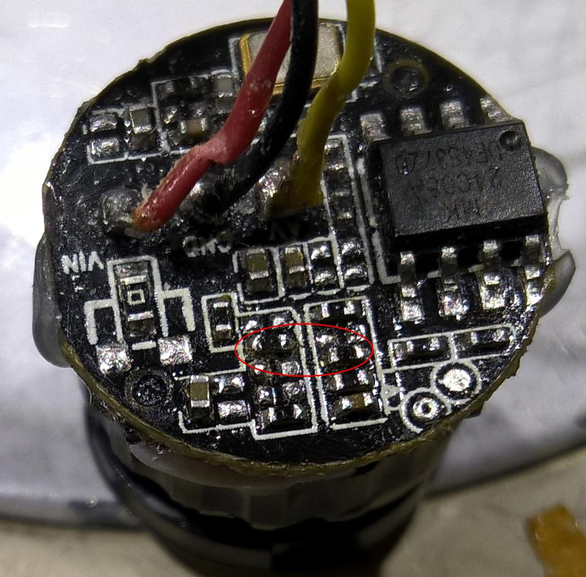
I opened up the back up camera that I bought on eBay for $3.72. The image quality is little poorer than the other one. The 4 LEDs are white light. After removing what appeared to be silicone gel and exposing the circuit board, I could see the imaging sensor and an EEPROM 24C08A, which is an I2C serial memory chip with 1Kx8 bits. It does not appear enough memory to supply the overlay image. So the OSD distance guideline displayed with the video is probably generated internally. I would like to remove the OSD and flip the image so it can be used as a front view camera.
The EEPROM has the three address lines grounded, so the 7-bit address is 0x50. The WP pin is also grounded allowing read and write. The I2C signals are pulled up to 3.3V with 4.7K. I started by shorting pin 4 (SDA) and pin 5 (GND) of the EEPROM. That probably forced the imager into the default state, but the default state enables the OSD with guidelines and a few extra numbers and letters and the exposure control seems a little different. So I'll have to get dump of the memory and make mods.