Monday, November 1, 2021

Thermostat

The check engine light came on and the code from the ODB port is P0128, which usually means the thermostat stuck open.  This is corroborated by the temperature indicator which does not rise quickly and stays below normal.  This is an emission related issue because the fuel does not burn completely in sub-normal temperature and more pollutants are released and the gas mileage is reduced.

After draining the coolant and removed the thermostat, the thermostat does not appear open.  A new thermostat is installed; the temperature indicator behavior is noticeably different: the initial temperature rises quickly and is  regulated to just below midscale.  Checking the thermostat operation by placing it in hot water, it opens as expected and closes as the water cools.  Why is it stuck open?  Close examination finds that the valve is not closed tightly; it is a little crooked, perhaps warped after many years of operation.  But it is still fairly remarkable that the thermostat is a simple robust mechanical design.  It is based on thermal expansion of material at relatively accurate temperature of 82C; it is submerged in hot liquid, no electronics involved, no energy needed.  Sometimes simple mechanical device is a better solution than electronic control.


Monday, August 9, 2021

An Update On AN8008 Multimeter

I wrote about the AN8008 multimeter.  I have been generally happy with the meter.  But more recently, I started to notice some problems: the meter sometimes does not start up correctly, I have to turn the rotary switch a few times; and more annoyingly is that the resistance measurements seem off: the shorted resistance can be 5 to 10 Ohms or more.  Initially, the meter also displays low-battery sign;  I measured the batteries; it seems that they should be OK.  But I changed batteries anyway, but the things did not improve.   I suspected that the rotary switch contacts might be the issue.  I opened it up and found solder flux residue on the PCB circular tracks that make contact with spring clip on the rotary switch.  I cleaned the board with alcohol; the flux was easy to clean.   After that the problem seems to go away; the probe short resistance is about 0.2 Ohm.  

It is interesting the flux residue that has migrated overtime since it was not a problem initially.


Sunday, August 8, 2021

More on Atomic Pi

I wrote about Atomic Pi about two years ago.  Recently, I started using it again as a desktop computer.  I like it for the quietness without a fan.  As a desktop computer, which it is not really intended for, it is under-powered.  The most severe limitation is the 2GB RAM (maximum possible for this Intel Atom processor), which is not enough to support web browsers' full functionality.   The SD card and the buit-in eMMC memory are relatively slow as a swapping device, especially writing (eMMC average  120MB/s read, 32MB/s write and 0.38ms seek).    A solid station disk on the USB 3 is a better alternative; the benchmark shows 417MB/s read, 396MB/s write and 0.24ms seek.  Initially I used a USB3 hub, but the disk is not working properly with the hub.  So the USB3 solid state disk is plugged into directly the lone USB3 port.  We still need a way to connect other USB devices, such as a keyboard and a mouse (although a Bluetooth keyboard/mouse is another option if no other USB devices are needed.). There is a USB2 port, but it is a 2mm JST connection.  So I had to make an adapter to connect with a USB hub.  The 5-pin connector pinout is GND, 5V, D-, D+, GND; I wired it a USB A female connector on a small proto board with a ribbon cable, with the shield grounded.  At least 2GB swap space is recommended.   Now it is usable as a desktop device.   I installed Lubuntu, the lightweight version of Ubuntu; it works adequately with multiple applications running.  I do not think Windows can run adequately.


Another device to explore is the XMOS processor that is used as an audio processor.  It appears programmable.  We'll see if we can do something with it next time.

Friday, April 30, 2021

Wireless Router

I have a couple of old routers that have been replaced by more advanced ones.  So it is time to hack them for other use.  A wireless router is an embedded computer with wireless connection; so it is good for IoT applications.  A lot of old inexpensive routers have 32MB RAM and 4MB Flash, which is rather limited for more advanced router application.  OpenWRT no longer supports this type routers.  It'll be good to branch off OpenWRT to support this type of routers for IoT.   We looked at one such router earlier.

Here we take a look at TP-Link TL-WR841N, Ver 9.2.  300Mbps wireless N router, with 4x 100Mbps ethernet ports.  The main components are

  • Qualcomm Atheros QCA9533-AL3A SoC
    • 24Kc MIPS processor with 64KB I-Cache and 32KB D-Cache at up to 650MHz
    • 25MHz clock input
    • 1.2V switching regulator for core voltage.  2.62V LDO for DDR1 and GPIO.
    • RF 20/40MHz band 2.4GHz OFDM for 802.11b/g/n, 2x RX/TX
  • Zentel A3S56D40GTP-50L 
    • 256Mb (16Mx16) 2.5v DDR400 200MHz @CL3xTSOPII-66.  
  • Spansion S25FL032P 
    • 32-Mb 3V Flash memory QUAD I/O 80MHz clock 40MB/s.  
  • BCD's AP3502E 
    • 340KHz fixed frequency 2A synchronous buck converter
    • 3.3V output
The PCB date code is 1434, about 2014 August time frame.  QCA9553 is more powerful and more integrated than AR9130 used on the other router.


J3 is a 4-pin UART connector,

  1. TX (2.6V)
  2. RX
  3. GND
  4. 3.3V
Note the I/Os are 2.6V.  TX has no problem driving 3.3V UART receiver; there appears to be a few resistors in series with the RX pin, so it could be driven with a 3.3V input, but it may be prudent to add another 1K resistor in series.

The last OpenWRT version for this router is openwrt-18.06.8.  We get the boot message from the UART, 

U-Boot 1.1.4 (Build from LSDK-9.5.3.16 at Nov 29 2013 - 10:46:36) ap143 - Honey Bee 1.1 DRAM: 32 MB Flash Manuf Id 0x1, DeviceId0 0x2, DeviceId1 0x15 Flash: 4 MB Using default environment

## Booting image at 9f020000 ...
   Uncompressing Kernel Image ... OK

Starting kernel ...

[    0.000000] Linux version 4.9.214 (buildbot@0d27b924961c) (gcc version 7.3.0
(OpenWrt GCC 7.3.0 r7989-82fbd85747) ) #0 Thu Feb 27 21:25:59 2020
[    0.000000] bootconsole [early0] enabled
[    0.000000] CPU0 revision is: 00019374 (MIPS 24Kc)
[    0.000000] SoC: Qualcomm Atheros QCA9533 ver 1 rev 1

BusyBox v1.28.4 () built-in shell (ash)
  _______                     ________        __
 |       |.-----.-----.-----.|  |  |  |.----.|  |_
 |   -   ||  _  |  -__|     ||  |  |  ||   _||   _|
 |_______||   __|_____|__|__||________||__|  |____|
          |__| W I R E L E S S   F R E E D O M
 -----------------------------------------------------
 OpenWrt 18.06.8, r7989-82fbd85747
 ----------------------------------------------------- 

We can interact with it through the ash shell.  Next we'll try to rebuild the firmware from the source and start to tweak.


Saturday, April 10, 2021

H632S-WC Weather Channel EZ Crank Radio Extreme


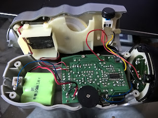
The crank is a 3-phase alternator driven by two-stage gears; the output is rectified by 6 diodes.   There is another diode between the bridge rectifiers and the output voltage.   The FM radio IC is CD9088CB, which can operate between 1.8V and 5V, drawing about 5mA.  The 8Ω 4W speak and earphone are driven by TDA2822M, a dual low-voltage power amplifier, which works down to 1.8V.  The rechargeable battery pack is a 3-cell NiMH for 3.6V.   Most other components are for the radio.   The rectified voltage is used for direct battery charging without regulation.  And the 5 parallel LEDs are powered directly with only small series resistors.  All the wire connections are fragile.   For a retail price of $15, we do not expect it to be a very robust construction.


The battery pack seems no longer can hold charge.  We'll replace it with a small 480mAh LiPo pack (1.2 x 1.0 x 0.3"), that costs about $6 and is a little smaller than the NiMH pack (1.2x1.2x0.42") .   We install a 2mm JST PH 2.0 2-Pin connector.

We bring out the voltage after the bridge rectifiers to the outside, so we can monitor the crank generator output and potentially use it to power other devices, such as other chargers.   The diode to the Lipo isolates the battery to these wires, so it is relatively safe.

When unloaded, the crank generates about 5-8V at a reasonable crank rate.  It can peak over 10V if cranked really fast.  When it is loaded with battery, the voltages does not exceed 4.5V; after diode drop, the voltage on the battery is only about 3.8V, so it is safety for the battery .  The generator can supply enough power to sustain the radio, but not the LED light.

We also connect the output to a boost regulator, that generates 5V.  We use the 5V to charge a Bluetooth earphone.   The generator puts out 4.4V/45mA, about 200mW.   The rectified output is not very stable.  If we take the output from the battery side, it's better.  If we use it to charge a smartphone, the crank cannot keep up and the internal battery drains first.