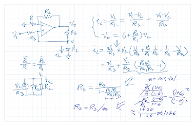
Here we derive the source impedance of the Howland current pump. The ideal current source impedance is infinity. The Howland current pump is depended on resistor matching. We consider the effect of mismatch on the source impedance.
Thursday, March 20, 2025
Howland Current Source Impedance
Sunday, March 16, 2025
A Current Source Circuit
As an application example, the data sheet of a shunt voltage reference presents an 1mA precision current source as shown here,
Normally, the negative feedback forces the input terminals of the opamp to be the same voltage and the output applies 2.5V across 2.49K to generate 1mA current to the load.
However, it is possible for this circuit to get stuck at the 0V. Note that the negative rail of the opamp is at the ground in the single supply configuration. With both opamp inputs at 0V, the offset voltage of the opamp causes the output to go to ground. This is a stable operating point if the offset voltage and the gain are in the right range.
If the opamp's negative rail is a negative voltage, the output saturates at the negative rail, the negative input is clamped at one diode above and the positive input would be more positive (except for certain loads) which would force the opamp out of saturation.
Is there a way to keep the circuit from settling in this undesirable operating point? One way is to inject some voltage on the opamp's positive input (diode blocking it after it is unstuck). The voltage divider can be adjust to minimize the error current. But invariably an error current (a few microamps) would go into the load if it has to operate over temperatures and a wide range of loads.


